This page documents a little project I did on the side just for fun. It is also a example of using the Embed Inc PIC development environment to build a simple one-module PIC project for a small processor (PIC 10F204).
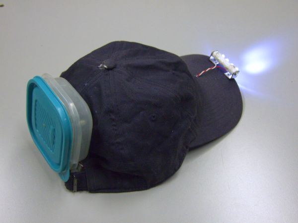
This project is the KnurdLight, which is a hat-mounted LED headlight that runs from two AA batteries.
A bunch of years ago I built a quick and dirty LED light the day before going camping in Maine for a week. I just wanted to get something working quickly and didn't have time for debugging and tweaking a circuit, and I had a bunch of small 3-cell NiMH batter packs that I wanted to use in the light. These put out nearly 4V when fully charged and about 2.5V when nearly empty. In the interest of just getting something working, I used a PIC with a really dumb algorithm that turned on a NPN transistor for a fixed time when the current sense voltage was too low. This wasn't intended to be a optimum design, but it worked very well. I used a 16F628 since that was the smallest suitable flash PIC I had lying around at the time.
That light worked nicely but the power supply with the battery pack and the PIC circuit had to be in the pocket with a wire running up inside my shirt to the LEDs on the hat. To switch it on and off, I had to plug or unplug the battery. This was quite good enough for a quick and dirty project, but after a while I wanted something different mostly for two reasons. First the custom NiMH packs I had gotten for the price of shipping were getting old and stopped holding charge, and there was no easy off the shelf replacement. Second, I didn't like the wire from the pocket running up to the hat.
For version 2, I decided to design something that would work from two standard AA batteries, preferably both primary and rechargeable. This time there was no time pressure. I had recently experimented with a pure analog circuit that would oscillate with down to 900mV power voltage. It could produce regulated 5V from a single cell. It was a free running low power oscillator with a few gain stages to turn the result into a full on/off signal that was used to drive the switching element of a boost converter. The feedback signal that indicated the output was above the regulation threshold turned on a transistor which killed the oscillation. It was simple but effective. I modified it for 20mA constant current output regulation and made a circuit board for it. The circuit board held the two batteries, the power supply electronics, a slide switch, and had two pads for the 20mA output. This was small and intended to be mounted on the back of a hat with wires to the front driving the same 4 LEDs as the previous version. The LED assembly was rather a kludge with plastic taken from a margarine container, some perf board for the LEDs, paper clips to hold the assembly on the hat brim, and gobs of epoxy to hold the LEDs firmly and to keep water off any bare connections.
The biggest problem with version 2 was that turning it on and off was awkward. The slide switch was easy enough to use, but making it accessible while trying to keep the circuit board out of the rain didn't work very well. I mounting the whole thing in a ziplock bag on the back of the hat. I figured it would be acceptable to open the bag to change the batteries and that I could slide the switch thru the bag. Changing batteries was OK, but working the switch thru the bag behind my head didn't work that well. The bag quickly developed holes, and I ended up leaving it open all the time. Fortunately I had at least put the opening at the bottom, so that kindof mostly worked. I had run the wires out the top, but never was able to seal that properly. I tried various glues and epoxy, but none of them adhered to both the bag and the wire and was flexible enough to take a little stress without separating and leaving a gap for water to get in.
The final straw that killed KnurdLight2 was that the TSA broke the LED assembly while rumaging thru my checked baggage on a trip to the annual Microchip Masters conference, after which I usually take a week off hiking around Arizona.
So on to version 3, which is the version featured on this web page. This time I wanted to address the watertight issues up front, and make the LED assembly more robust. I still wanted it to run from two AA cells, since they are widely and cheaply available. I also decided this is really not a good application for rechargeable batteries since the light sits for long periods of time, and then needs to come on reliably on short notice. A pair of AA primary cells should run the light for something like 20 hours using conservative efficiency estimates. That means you can get by with taking only a single pair of spare batteries even if you'll be away from civilization for days. 20 hours of actual run time is a long time when all you need is a few minutes to a hour or two here or there.
The biggest problem with making version 2 watertight was accessing the slide switch to turn it on and off. I figured a pushbutton would be easier to access thru a watertight enclosure, but you don't want the light to come on when something gets accidentally pressed on or bumped around. Also how do you use a single button to toggle between on and off, and use virtually no current when off?
My solution was to manage the button logic in a processor where I could apply a far more complex algorithm than could be easily realized with analog electronics. And if I was going to have a processor in there anyway, it might as well be running the power supply too.
The PIC 10F204 is a great little processor for this application. It has a comparator and a absolute 600mV reference that can be internally tied to one of the comparator inputs. All it needs is a analog voltage that indicates the regulated output is high or low by being above or below 600mV, and the PIC can control the boost power supply directly. Since the output is supposed to be regulated 20mA, providing the feedback signal is as easy as using a 30 ohm low side current sense.
With a processor handling the button, the logic could be anything I wanted. I made it require two presses to turn on, with the presses and the pause between them each about 1/2 second. That is still easy to do when you want to, but not that likely to happen by accident. Any press of the button turns the light off when it is on. So if something is randomly pressing the button, the light will come on infrequently, but go off on the very next press regardless of timing.
For the enclosure I used the smallest tupperware-like container I could find. The one used is still bigger than needed, but that's what was available. These containers seal well, so the enclosure is nicely watertight. The enclosure is certainly not optimal, but works well enough. There is also a certain geekness factor about wearing a tupperware container on your hat.
Here is what it looks like inside the container:
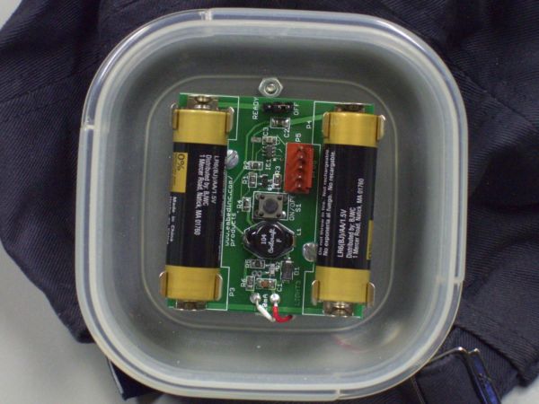
The pushbutton is right in the center, and can be pressed thru the lid via a small plastic rod mounted on the underside of the lid:
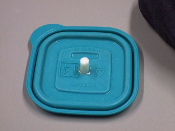
There is a few millimeters of travel before the rod touches the pushbutton so that you have to deliberately press on it. This scheme may sound complicated, but actually works very well and is a lot easier to use than it probably sounds. Putting the pushbutton and the rod in the center is important. That way the lid can go on rotated any of the four ways.
The LEDs are mounted on another plastic rod:
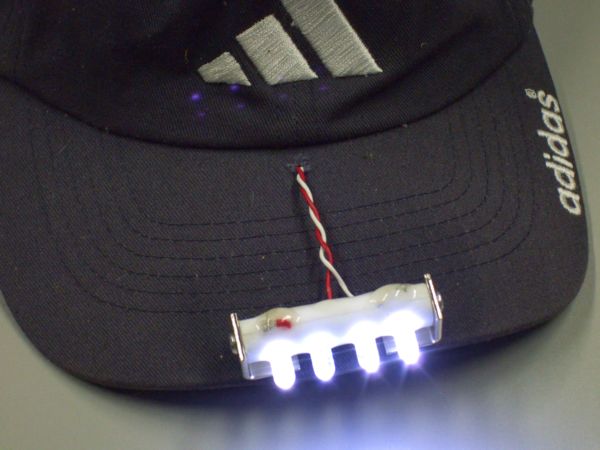
The LED leads go thru holes drilled in the plastic rod and are connected in series on the opposite side from the LED bodies. The red and white lead wires carrying the regulated 20mA are then connected to the ends of the series string of LEDs. All the connections are made watertight and insulated with gobs of epoxy. Not ellagant, but effective. The epoxy also holds the LEDs in place. Angle brackets hold the plastic rod at its ends and mount the whole assembly to the hat brim. The LED rod is held tight enough so that it doesn't move on its own, but can be swivelled up and down to adjust the beam high or low. Here is a closeup of the LED assembly with the light off to make it easier to see the details:
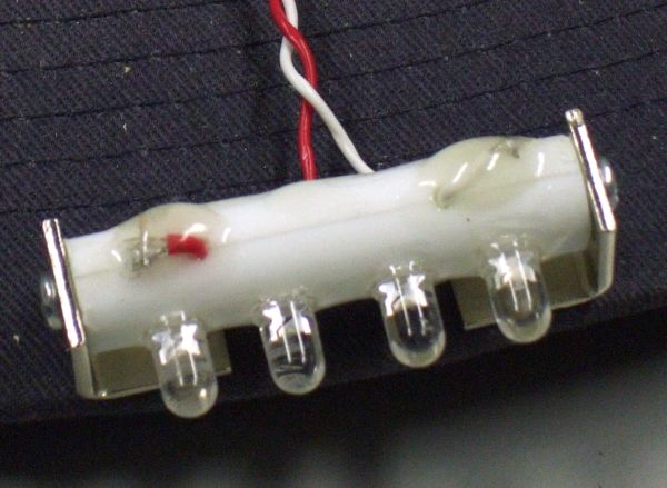
The two plastic rods used in this project (pushbutton presser, LED assembly) came from a plastic coathanger. The plastic is flexible enough that it won't easily break, but stiff enough for the job with these short lengths.
The firmware with build script and other associated files is available from the downloads page. Note that the INSTALL_PIC_KNLI release is a incremental release and requires the PIC development environment at minimum to also be installed for the firmware to be buildable. The KNLI project source code will be in the SOURCE > PICS directory within the software installation directory. When everything is set up correctly, the script BUILD_KNLI_EXPIC will rebuild the PIC firmware.